Older corded and early cordless drills used brushed motors — carbon brushes physically riding on a commutator, wearing down over time but electrically simple. Modern tools like this Milwaukee use a brushless (BLDC) motor instead: no brushes to wear out, but the trade-off is that the motor cannot commutate itself. All of that switching is handled by a small power stage bolted straight to the motor, and that power stage is exactly what failed here.
How a brushless drill motor actually gets its power
A BLDC motor has three stator windings (commonly labelled U, V and W) surrounding a permanent-magnet rotor. To make the rotor spin, the controller energises those three windings in a precise, repeating sequence — not all at once, and not randomly. Three Hall-effect sensors sit inside the motor and report the rotor's exact position back to the controller board in real time. Based on that position feedback, the controller switches power to the correct winding at the correct instant, so the stator's magnetic field is always just ahead of the rotor's magnets, pulling it around. Get the timing wrong and the motor stalls, judders or draws heavy current without turning at all.
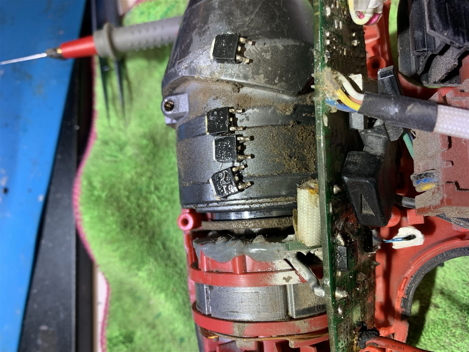
What the MOSFETs do and how they're wired in this drill
A MOSFET here is nothing more than an electronically controlled switch. Apply a voltage to its gate pin and current flows freely between drain and source; remove it and the switch is open. In a compact tool controller like this one, each of the three motor phases has its own N-channel MOSFET doing the low-side switching for that winding — connecting it to the negative side of the battery pack for a precisely timed slice of every commutation cycle. The fourth MOSFET sits in series with the main battery feed itself, acting as the master power switch for the whole drive stage. It's what lets the controller cut all power instantly when you release the trigger, and it's also usually what implements electronic braking — momentarily connecting the motor phases together to bring the chuck to a dead stop instead of coasting.
All four gates are driven by a small control IC on the green PCB, which reads the three Hall sensor wires and switches the MOSFETs on and off thousands of times a second to both commutate the motor and regulate speed with the trigger.
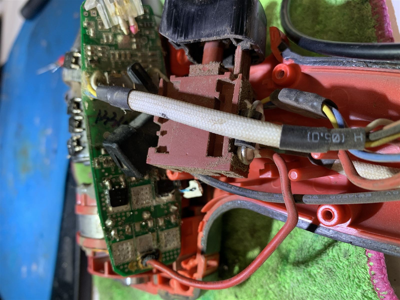
Why all four MOSFETs failed at once
A single shorted MOSFET is common — a locked rotor, a jammed bit or a stall under heavy load can push instantaneous current through one switch well past its rating and take it out on its own. Four failing together points to something bigger hitting the whole stage at once, and on this board there are two obvious contributors:
- A hard stall or reverse-EMF spike. If the bit binds hard while spinning at full speed, the sudden mechanical stop dumps a large, uncontrolled current spike back through the drive stage. If that spike lands while more than one phase is conducting, it can take out several MOSFETs in the same instant.
- Cascading failure through the shared gate rail. Once one MOSFET shorts drain-to-source, it can pull the shared battery rail or gate-drive supply out of spec for the others, feeding them an incorrect switching condition. What starts as one dead switch becomes four in a fraction of a second.
- Contamination bridging the board. The heavy dust caked over the motor can and the exposed FET legs in these photos is a real factor — fine conductive grit from site work (masonry, drywall, timber dust mixed with moisture) can settle across leads and pads, creating a partial short that stresses every switch on the rail simultaneously rather than failing cleanly.
In practice it's often a combination: dust ingress lowers the board's tolerance for a current spike, and then a stall under load is what actually pulls the trigger on the failure.
How we actually repair it
Each MOSFET gets tested in-circuit first, in diode mode, to confirm which ones are genuinely shorted drain-to-source rather than just reading low because of surrounding components. Because four switches failed together, the control IC and its gate resistor network get checked too — a driver IC that fed a fatal condition to the gates is a common reason a repair "holds" for a week and then fails again. Once the fault map is confirmed, the shorted MOSFETs are desoldered and replaced with correctly rated parts, the board is cleaned of flux and residue, and every phase is re-tested for correct switching resistance before the board goes anywhere near the motor. Only after the Hall sensor signals and all three phases check out on the bench does the drill get reassembled and test-run under load — the same diagnose-before-you-quote approach we use on any board-level repair.
Getting more life out of a cordless drill
- Don't fight a stall. If the bit binds, let go of the trigger immediately rather than pulsing it — repeated stall current is the single biggest killer of a brushless controller.
- Use the clutch and the right speed setting. Driving screws or drilling on a setting that makes the motor labour constantly puts the drive stage under load it wasn't sized for.
- Blow the tool out regularly. Compressed air through the housing vents after site work — especially masonry, timber or drywall jobs — stops dust building up on the board and motor can like it has here.
- Keep it dry. Dust plus moisture is what actually bridges pads and legs. Let a wet tool dry out fully before it's used or packed away.
- Use a genuine, matched battery pack. Off-spec or worn-out third-party packs can deliver current spikes or sag in ways the controller wasn't designed to handle.
- Avoid drops onto hard surfaces. A shock can crack a solder joint on the controller board that doesn't fail outright until weeks later.
Cordless drill or driver not spinning up?
CQ Electronics diagnoses power tool controllers at board level before quoting — phones, tablets, laptops, consoles, ECUs and vehicle electrical work, in Brisbane.
Request a quote →